


Sieve trays The sieve trays have been developed when the hydrocarbon industry and the oil and gas industry have extended.
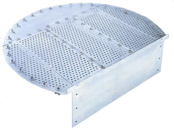
Single pass sieve tray DN 1600 in stainless steel
Three trays are very cheep ones and their maintenance is easy. In an other hand their turn down ratio is quite low (1 to 3) and their yield is also relatively low especially when the liquid load or the vapour load is low. Most of the sieve trays are designed with 12 mm diameter holes. However some sieve trays may be designed with larger holes ( 25 mm ) mainly the liquid load is very high. In an other hand when a high efficiency is required we may reduce the diameter of the holes down to 6 mm .
Operation principle The liquid is flowing from one tray to the next one by gravity and the vapour is coming up trough the liquid. Some elements originally in the liquid are “vaporated” in the vapour and some elements originally in the vapour are “dissolved” in the liquid. This mass transfer may take place in a distillation as well as in absorption.
Erection and layout The sieve trays as every tray are designed in elements, which may be introduced through the manhole of the column and are generally fitted on a circular ring by clamps For a good operation the flatness of the trays is very important. Up to three meters of diameter, the beam incorporated to the tray will lead to a satisfactory flatness ; above it a support beam is generally recommended. The spacing between the trays is an important concern a major part of the mass transfer is made between the trays. We generally recommend 600 mm , but for lower diameter (less than 1 meter ) we might design the spacing down to 400 mm . The sieve trays are generally designed with lateral weirs, bit for high diameter (above 2 meters ) central weirs may be required in order to better distribute the liquid phase.
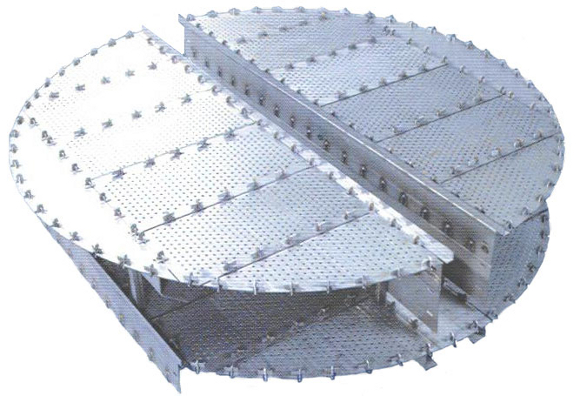
Double pass sieve tray DN 2800 in carbon steel
|