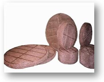


Knitted mesh pads Knitted mesh pads are coalescing internals made of several layers of corrugated knitted mesh layers made from a stainless steel or a plastic wire. This pads are used to pick up the liquid particles from a gas stream. KEMPRO manufactures several types of knitted mesh pads. They are identified by their specific surface which is the contact area per volume unit (m 2 /m 3 ). The main types manufactured by KEMPRO are the following : D150- D200- D270- D350- D450 – P250
Mesh pad in PPH
Operation principle The liquid particles carried over by a gas stream enter inside the pad with more inertia than the gas molecules. In the changes of direction due to the presence of knitted wires, the droplets gather themselves on the wires by wetting them up to a sufficient size to drop by their own weight.
Efficiency The efficiency of the knitted mesh pads is expressed by the size (in micron) of the droplets caught at more than 99,5 % supposing the operation conditions are within the recommended limits. The efficiencies of the main types of knitted mesh pads are summarized in the table below:
The above mentioned efficiencies are actual if the operating conditions are within be following limits :
Operating conditions - Optimum velocity : the gas velocity inside the knitted mesh pad must not exceed a maximum velocity (V max) and must be higher than a minimum velocity (V min) :
with, k = 0,14 m/s (for V max) k = 0,11 m/s (for V design) k = 0,035 m/s (for V min) with, r L = liquid density at the operating conditions (kg/m 3 ) r G = gas density at the operating conditions (kg/m 3 )
- Liquid rate : The ratio of actual volumetric flow rates (liquid/gas) must be high enough to let the mesh pad wet. This rate must exceed 10 -5 . If this is not the case, a wetting system must be provided. In addition to it the specific liquid flow rate must exceed a limit value :
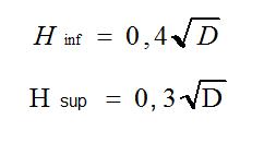
- Disgaging height : The gas flow must be equally disposed in the knitted mesh pad in order to avoid any by-pass. To do so a minimum height must be provided above (H sup ) and under (H inf ) the knitted mesh pad. These heights are expressed in meters by the following formula as a function of the pad diameter (D in m) :
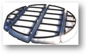
Knitted Mesh pad in AISI 316L
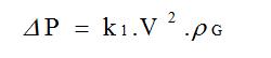
Pressure drop When flowing through the knitted mesh pad, a very weak pressure drop occurs. It may be expressed as a function of the gas velocity (in m/s) and of its density r G (in kg/m 3 ). The following formula is valid for a mesh pad of 100 mm thickness (100 is the required height for performing the service) :
Fig. 2 : Value of k1
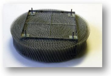
Knitted Mesh pad D350
Erection and layout The mesh pads are delivered in elements which may be introduced through the separator man hole. To allow their fixing they are manufactured together with their support grid and hold down grid consisting mainly in bars of 25 mm height welded together trough rods (generally 6 mm diameter) crossings the whole pad in its thickness. The different elements are assembled one against each other. As the pads are designed somewhat larger than the separator, the pads are assembled inside the separator by compressing them slightly on their sides to get no gas bypass between the separator and its pad. Every mesh pad element is generally tightened on a support ring by clamps.
|